General Info:

For this project, our objective was to build a voting machine (CDS and breadboard) where if four board members vote, majority wins and a tie is decided by the president's vote. The designed circuits in all cases had to be built with 2-input gates.
|
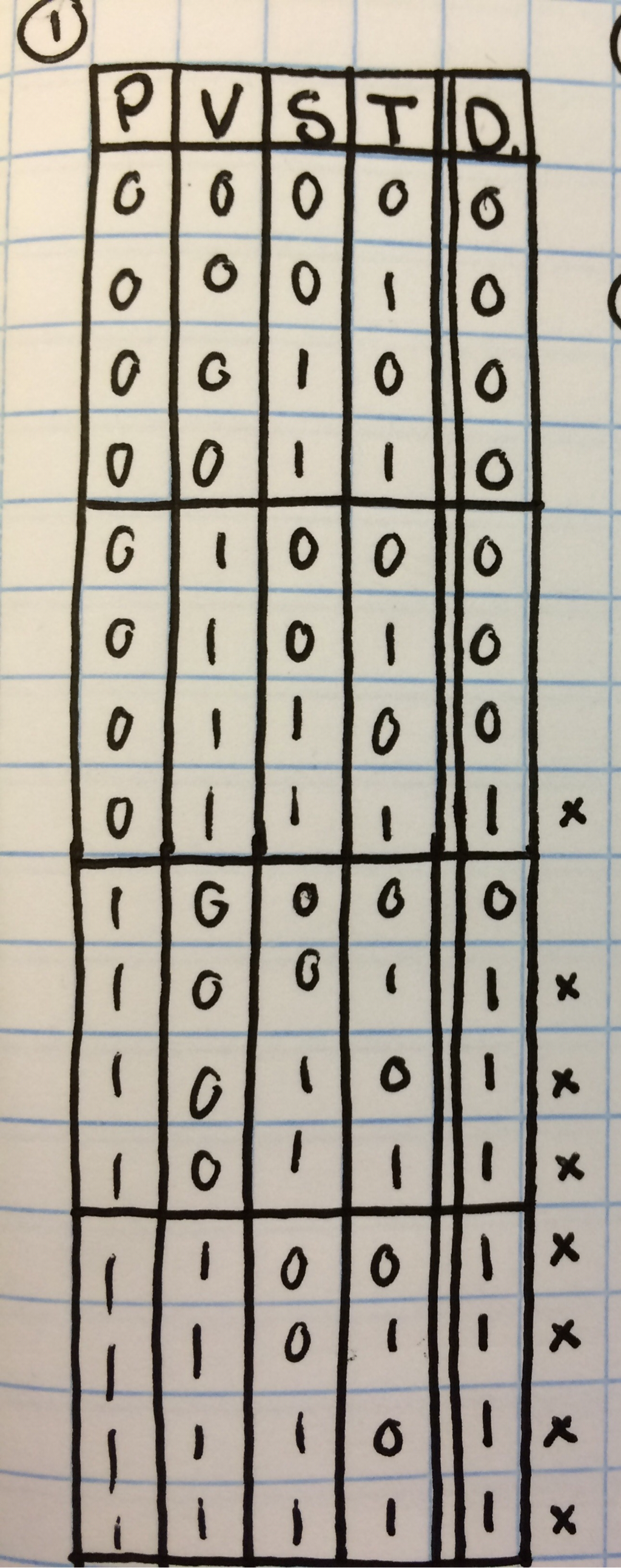
Truth Table and Expression:This truth table describes all possible outcomes of the voting machine and whether the vote would pass or not. Because the circuit has 4 variables, there are 16 possible outcomes (2^4). As you can see, when the vote is tied, the president's vote decides the outcome. Possibilities with a 1 in the D column (Decision) or an x next to the row are all outcomes where the vote was positive and are called minterms.
|
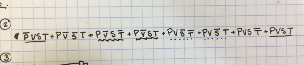
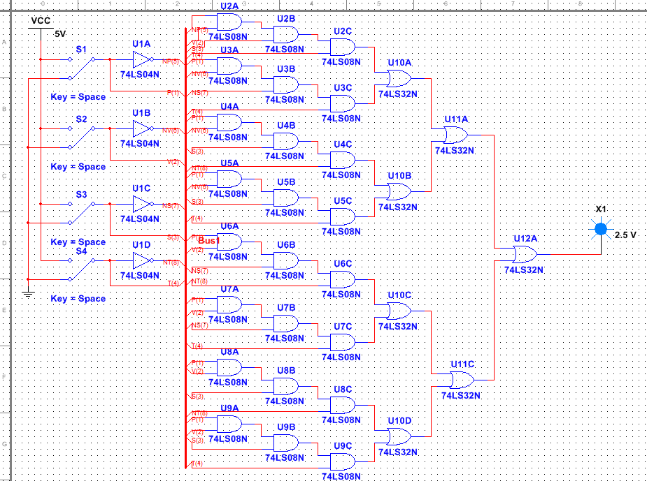
Here in the unsimplified logic expression, I added all the minterms to form this complicated and unsimplified mess, which is represented in the below circuit design. The design is messy because we had to code in each solution to the expression individually instead of condensing it. This would be a nightmare to breadboard, with 31 gates in all and requiring 1 NOT chip, 6 AND chips, and 2 OR chips.
Simplification:
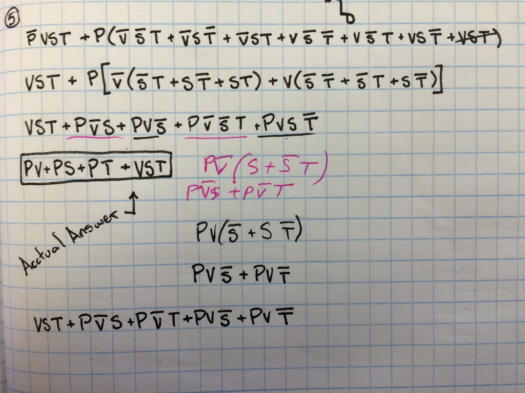
This was the simplification process that I used to get the final equation for the circuit.
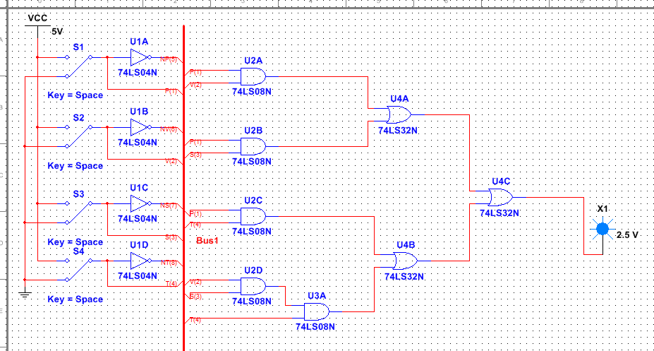
This simplified version of the circuit uses just 8 gates and requires 2 AND chips and 1 OR chip. Having 23 less gates than the last circuit, this one is much easier to build and much less wasteful. Using a bus is also a useful too I used to prevent wire clutter.
Circuit Building:
MATERIALS:
- 1 Breadboard
- 1 Breadboard Companion
- 1 3.3 k Ohm resistor (+-5%)
- 1 LED
- 2 74LS08 (AND) gates
- 1 74LS32 (OR) gate
- x amount of wires
Using the simplified circuit design on multisim, we had to breadboard a working circuit. Each wire had to be connected to the pegs of the IC's and the outputs connected to the next step in the sequence. It was much more complicated that the design, but mine ended up working pretty fast. The only mistake that I made was not connecting both sides of the board for the P output.
Conclusion:
Overall this was a fun project and I enjoyed doing it. Completing the unsimplified circuit in multisim was not the highlight of the venture, and took about a solid hour of clicking, but it was made much easier and clean looking with the use of the bus tool. Once simplified, the circuit was very condensed, having 8 gates instead of the previous 31. I'm not much for Boolean algebra, but eventually the equation got simplified and I was able to progress through the project. The math was hard, because the amount of simplification that you could do to it was all based around how you grouped the terms together. My favorite part of the project was definitely the breadboarding. It was like a puzzle, and had to be figured out through vague instructions. Near the end of the construction, the wiring began to get tangled and complicated, making it hard to decipher what you were doing or correct any small mistakes My circuit worked second try, after a mistake with bridging the gap on the board, so really I had no major errors with the design itself. So now I actually understand breadboarding if not complex Boolean logic, but I definitely enjoyed the project.
